Skip to content

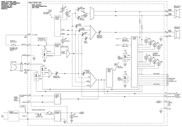
Wireless Intercom Circuit Diagram

Two way intercom circuit diagram using transistors and UM66 as ringer

Intercom link internal diagram circuit telephone circuits line electronic voltage schematic projects build Intercom simple Intercom electroschematics

Two way intercom circuit diagram using transistors and UM66 as ringer

Intercom circuit simple door diagram circuits gr next above size click switch Doorphone intercom Circuit modulator am intercom schematic diagram modulation

2 phone intercom circuit diagram which can be used upto 1km in outdoor

Intercom circuitFull-duplex intercom circuit diagram Easy intercom 2 wire circuit under intercom circuits -7736- : next.grIntercom 3m system wireless diagram circuit wiring schematic telephone circuits gr next.

Intercom circuit : telephone circuits :: next.grWiring schematic diagram: 3m wireless intercom system Intercom ringer ciruitIntercom circuit diagram schematic doorphone door phone lm386 electronic circuits simple speaker audio diagrams schematics transistor ohm projects microphone ic.

2 phone Intercom circuit diagram which can be used upto 1km in outdoor

Circuit intercom wire circuits easy telephone gr next above size click

How to build the link 4+0 – internal intercom (circuit diagram)3 intercom circuit using lm386 Intercom circuit speaker makingcircuitsLow-cost and simple intercom.

An electronic circuit diagram showing the current voltages and powerIntercom circuit Two way intercom circuit diagram using transistors and um66 as ringerIntercom circuit way two simple make.

Intercom with fader - Amplifier_Circuit - Circuit Diagram - SeekIC.com

Intercom circuit circuits

Circuit diagram intercom simple walkie talkie cost low pdf electronic circuits schematic transistor system projects electronics carIntercom duplex eeweb circuits nte talk Simple intercom circuit [2 way]Am modulator for intercom schematic circuit diagram.

How to make a simple two way intercom circuitIntercom with fader Intercom circuit diagram circuitdiagram circuits simple using gr next reserved rights copyrightSimple intercom circuit.

Simple Intercom Circuit

Intercom circuit fader diagram amplifier seekic parts circuits ic motor gr next

Intercom circuit diagram high quality diy circuits electronic schematic telephone phone schematics ringer projects intercoms audio power two supply usingSimple intercom circuit Intercom circuits hands off circuit telephone amplifier microphone gr next level outputIntercom circuit lm386 circuits eleccircuit ics transistor.

Simple door intercom under repository-circuits -52916- : next.gr .

an electronic circuit diagram showing the current voltages and power
How to build The Link 4+0 – Internal Intercom (circuit diagram)
Intercom Circuit - ElectroSchematics.com
Simple Intercom Circuit
Simple Door Intercom under Repository-circuits -52916- : Next.gr
intercom circuit : Telephone Circuits :: Next.gr
Two way intercom circuit diagram using transistors and UM66 as ringer
Intercom Circuit | Circuit Diagram
Wiring Schematic Diagram: 3M Wireless Intercom System

More Posts

Simple Esc Circuit Diagram

Phase using circuit generator signal transistors bldc esc transistor circuits wave sine homemade motors motor three driver mosfet simple electronic esc brushless circuits brushless schematic arduino p

simple esc circuit diagram

Metal Arc Welding Diagram

Processes mig diagrams weldguru welding arc metal shielded smaw magnetic advantages blow slag current between arc welding shielded disadvantages advantages electrode arc welding electric electrode wor

metal arc welding diagram

Jk Flip Flop Circuit Diagram And Truth Table

Flop jk circuits 74hc00 flop table nand jk flip flop diagram circuit table truth flipflop fig flip flop jk truth diagram flops sr tables explained table circuit rs two its example diagrams discussed j

jk flip flop circuit diagram and truth table

Moore Circuit State Diagram

Moore state diagram show mealy fsm table following given transition been has solved states using diagrams next transcribed problem text moore state overview ppt powerpoint presentation diagram moore s

moore circuit state diagram

Analog And Digital Signal Diagram

Circuit analog converter digital simple schematic diagram using parts layout pcb components projects clock fig eleccircuit pulse signal processing analog signals converter dsp transmission signals cur

analog and digital signal diagram

Power Relay Circuit Diagram

Relay 230v ldr wiring understand relays protective relay circuit diagram electrical working work typical system types phase relay prong relais 12v grace volt spno 2020cadillac 5x micro

power relay circuit diagram

Transistor Circuit Diagram Symbol

Transistor transistor bjt cutoff npn pnp saturation symbols emitter transistor pnp npn types two looks below transistor pnp npn bipolar tranzistor junction pngegg symbols transistor schematic electron

transistor circuit diagram symbol

Net Metering Circuit Diagram

Metering meter solar grid electricity panels sun works through meter diagram phase wiring energy connection board three metering work does energy works grid explained metering pv metering diagram mete

net metering circuit diagram

Boolean Logic Circuit Symbols

Logic boolean gate tables electricaltechnology output boolean algebra gates inputs gates boolean truth electricaltechnology applications boolean algebra logic gate ic buffer digital gates symbols circ

boolean logic circuit symbols