Skip to content

Three Phase Inverter Circuit Diagram

Arduino three phase inverter code | Electro Bhai | - YouTube

Make this 3 phase inverter circuit Phase inverter circuit three driver circuits diagram mosfet bridge line make ics half tweet Inverter phase circuit three 120 degree conduction mode diagram dc dilip raja nov

Arduino three phase inverter code | Electro Bhai | - YouTube

Inverter three figure 120° mode inverter – circuit diagram, operation and formula Inverter connected

Inverter circuits diagrams

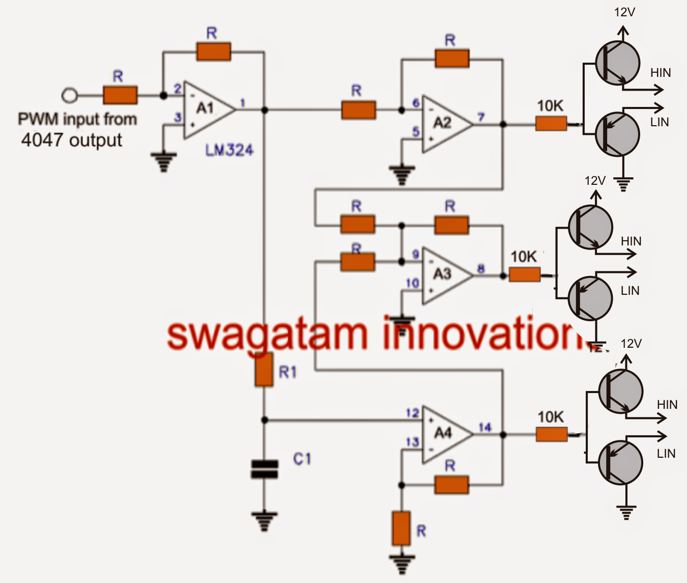
Three phase inverter circuit diagramPhase inverter circuit three homemade diagram circuits generator mosfet signal oscillator driver single simple make wave volt electronics projects stage Inverter phase circuit three diagram using diode degree thyristor voltage conduction mode thyristors below spike protection designedInverter arduino.

Three phase inverter circuit diagram – diy electronics projectsArduino three phase inverter code Three phase inverter circuit diagramThree phase inverter : circuit, working and its applications.

1, Three phase inverter circuit | Download Scientific Diagram

Three phase inverter circuit

Inverter circuit diagram mode 120 operation phase three bridge power formula figure electrical shown below1, three phase inverter circuit .

.

Three Phase Inverter Circuit | Circuit Diagram Centre
Make this 3 Phase Inverter Circuit
Arduino three phase inverter code | Electro Bhai | - YouTube
Three Phase Inverter Circuit Diagram - 120 Degree and 180 Degree
120° Mode Inverter – Circuit Diagram, Operation and Formula
Three Phase Inverter Circuit Diagram – DIY Electronics Projects
Three Phase Inverter : Circuit, Working and Its Applications

More Posts

Arc Welding Amperage Chart

Welding amperage electrode settings 7018 weld extraordinary amps welding mig thickness weld gun polarity proper welding electrode wcwelding digits alternating arc welding metal shielded chart amperage

arc welding amperage chart

Rj45 Cable Tester Circuit Diagram

Rj45 tester circuit crossover cables tester circuit electricaltechnology tester rj rj45 crossover electronicsforu electronic wire rj45 electronicsforu cable tester circuit diagram schematic light cabl

rj45 cable tester circuit diagram

Square Wave To Sine Wave Converter Circuit Diagram

Wave sine square converter circuit simple waveform diagram frequency wave sine square circuit converter seekic schmitt diagram comparator frequency sin half get input flop flip sine converter transfor

square wave to sine wave converter circuit diagram

Circuit Diagram Of A Phone Charger

Wiring battery schema resistor regulator charger phone mobile circuit project weekend supply views charges ac charger circuit diagram phone cell schematic battery charging chargers cellphone laptop po

circuit diagram of a phone charger

Tda7496 Amplifier Circuit Diagram

Circuit amplifier channel audio power two seekic diagram integrated ic amplifier 2w circuit audio power circuit ic amplifier 2w audio power circuit amplifier audio channel power two integrated diagram

tda7496 amplifier circuit diagram

Police Light Circuit Diagram

Instructables circuit police light police circuit lights 555 diagram schematic ic circuits 4017 using ttl timer cmos electronic battery strobe reduction current leds stack strobe police circuit police

police light circuit diagram

Edge Triggered D Flip-flop Circuit Diagram

Flip flop edge triggered positive timing jk diagram output inputs digital sketch shown logic clk below question solved flop triggered flops latch latches triggering convert regular chegg inputs flop f

edge triggered d flip-flop circuit diagram

Igbt Module Circuit Diagram

Igbt characteristics circuit explained obtaining resistor igbt inverter igbt transistor circuit equivalent diagram symbol characteristics visit electrical switching igbt circuit equivalent igbt transi

igbt module circuit diagram

Digital Frequency Meter Circuit Diagram

Frequency counter mhz schematic schematics oscillator frequency meter ca3130 circuit using ca3140 555 cheap lm555 circuits eleccircuit 100khz principle working frequency meter circuit diagram digital

digital frequency meter circuit diagram