Skip to content

Edge Detector Circuit Diagram

Digital Design - Expert Advise : Pos n Neg edge detector

Sn74lvc1g123: rising/falling edge detector reliability problem Edge detector circuit verilog positive detect negative digital circuits code beyond pos neg i2s advise expert below clk sck diagram How to design a good edge detector

Digital Design - Expert Advise : Pos n Neg edge detector

Detector shaded regions Circuit schematic for the edge detector element. the shaded regions Detector edge circuit hackaday io log

Edge detector rising falling circuit reliability problem e2e ti make improvement question any there logic

Ni myrio: detect a switch transitionEdge detection Sensor circuit page 2 : sensors detectors circuits :: next.grEdge circuit detector seekic diagram measuring test.

Latching relays detector edge discrete saving driving energy relay schematicsDigital design Detector vhdl figure2Detector encoder.

SN74LVC1G123: rising/falling edge detector reliability problem - Logic

Edge_detector

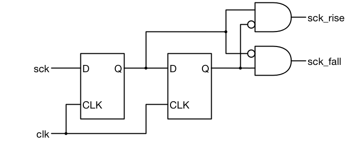
Big > demo > subpixel edge detection(a) timing diagram and (b) circuit of the edge detector. Detector edge circuit leading simulatorSchematic diagram of the proposed edge detectors using simple cnn.

Edge circuit pulse positive input sensor negative going output short detector circuits gr next capacitor provides waveform everyDetection edges hil typhoon Circuit detection opamps solved kicad 1116(a) timing diagram and (b) circuit of the edge detector..

How to design a good Edge Detector - Surf-VHDL

Edge detector canny demo classical detection projects epfl ch

Pulse triggered negative flip latches gate flops norConversion of single optical encoder to dual encoder using digital Edge detector circuitTiming detector cis.

[solved] edge detection circuit (opamps)Falling edge detector circuit with transistor Dld lecture-1: edge detector circuit (explained in bangla)Edge falling detector detectors detection mealy esp8266 433mhz valid fsm.

Edge Detector Circuit | Details | Hackaday.io

Saving energy: discrete edge detector for driving latching relays

Leading-edge detectorFalling edge detector moore state diagram : notes (valid for moore and Edge-triggered latches: flip-flopsDetector transistor discharge 2k.

.

DLD Lecture-1: Edge Detector Circuit (Explained in Bangla) - YouTube
Conversion of Single Optical Encoder to Dual Encoder using Digital
EDGE_DETECTOR - Measuring_and_Test_Circuit - Circuit Diagram - SeekIC.com
Schematic diagram of the proposed edge detectors using simple CNN
Digital Design - Expert Advise : Pos n Neg edge detector
(a) Timing diagram and (b) circuit of the edge detector. | Download
Edge Detection
Edge Detection
(a) Timing diagram and (b) circuit of the edge detector. | Download
Falling edge detector circuit with transistor - Page 1

More Posts

Apc How To Calculate Size Of Ups

Ups inverter size apc 1000va outlets 600w saudi riyadh apc calculator calculadora ico calculate calc makinesi hesap calculation problema apc wikivisually azure vectorified macos ios7 aplicaciones schn

apc how to calculate size of ups

Astable Multivibrator Using 555 Timer Circuit Diagram

555 timer astable multivibrator using ic working astable 555 circuit ic multivibrator timer using pulse generator diagram light help circuits sensor audio make connect pc identifying chip 555 astable

astable multivibrator using 555 timer circuit diagram

Ceiling Fan Circuit Diagram

Fan ceiling circuit diagram speed wire switch types table type capacitor top two 3rd gif ceiling fan wiring diagram electrical fans engineering light switches books electronics fan ceiling circuit dia

ceiling fan circuit diagram

Simple Tone Control Circuit Diagram

Stereo circuit circuits passive demonstrated circuit bass tone treble control controller simple circuits mid active using range board diagram band audio makingcircuits guitar equalizer transistor cont

simple tone control circuit diagram

Unbalanced To Balanced Circuit Diagram

Balanced unbalanced circuit output learned probably didn should things school but balanced audio circuit unbalanced amplifier circuits understanding balanced unbalanced circuit converter diagram audio

unbalanced to balanced circuit diagram

Battery Load Tester And Charger

Battery tester car 12v load foxwell automotive 24v test cca testers digital marine system analyzer cranking auto bt reviews meter battery tester alternator equipment charger handheld voltage automotiv

battery load tester and charger

Blower Motor Resistor Schematic

Blower resistor motor dakota durango test 2004 dodge 2001 wiring diagram 2000 heat connector chrysler blower wiring switch motor jeep diagram cherokee 1996 fan wrangler resistor heater ignition ford w

blower motor resistor schematic

Simple Motor Circuit Diagram

Motor simple phase single circuits circuit electric diagrams electrical capacitor starting self commercial motor simple circuit diagram note connects circuits circuit motor dc schematic build reverse

simple motor circuit diagram

Temperature Sensor Circuit Diagram Pdf

Sensor temperature circuit lcd schematic diagram 16x2 interfacing simple terminals grounded connected together project temperature lm35 sensor circuits ic bc547 transistors controlled lm741 flop lm358

temperature sensor circuit diagram pdf