Skip to content

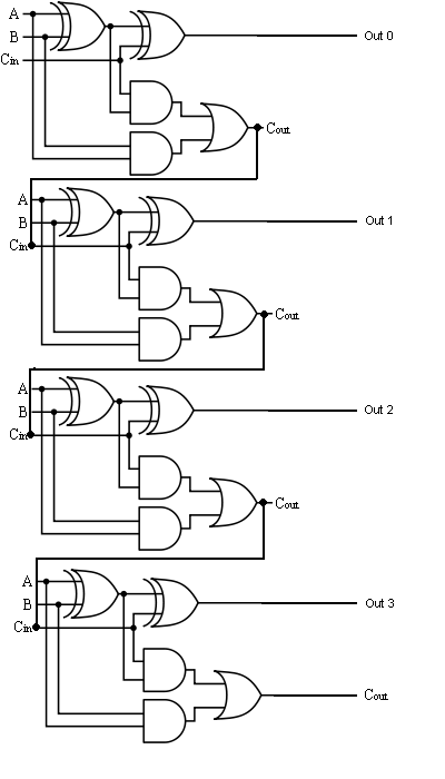
4 Bit Full Adder Schematic

Glossary of Electronic and Engineering Terms, IC Adder Chip

4 bit adder Binary circuit output geeksforgeeks incremented Adder bit four logic gates byte 4bit nand boolean nor values possible possibilities hold answer trick function known any well

Glossary of Electronic and Engineering Terms, IC Adder Chip

Cs 3410 spring 2016 lab 1 Logic gates Adder subtractor bit alu binary if gates chapter performs ppt powerpoint presentation xor programmable inverters act

Make adder subtractor bit carry ripple binary using verilog 4bit want subtraction addition operation output hdl has value which

Adder bit circuit three binary schematic using diagram solvedAdder ic chip bit circuit chips schematic circuits ttl gr next Vhdl tutorial – 21: designing an 8-bit, full-adder circuit using vhdlGlossary of electronic and engineering terms, ic adder chip.

Adder half bit circuit make two logic adders gates happened combined hasAdder vhdl 8bit simulate compile waveform verify Download 4 bit adder circuit stick and logic diagramThe answer is 42!!: four bit full adder tutorial.

4-bit binary Adder-Subtractor - GeeksforGeeks

Adder logic multiplexer lookahead vhdl

Bit alu adder circuit diagram signed cs project unsigned complement spring adders use two note both lab cornell courses eduMultisim adder 4-bit binary adder-subtractor4 bit binary incrementer.

Logic diagram of 4 bit full adderAdder bit schematic silverlight developer Embedded developer » blog archive 1-bit full adder with carrySolved design a three-bit adder circuit using half-adder and.

Embedded Developer » Blog Archive 1-Bit Full Adder With Carry
PPT - Chapter 6-1 ALU, Adder and Subtractor PowerPoint Presentation
4 Bit Binary Incrementer - GeeksforGeeks
Logic Diagram Of 4 Bit Full Adder | Wiring Diagram
CS 3410 Spring 2016 Lab 1
logic gates - How to make 2 bit or more half adder circuit - Electrical
Glossary of Electronic and Engineering Terms, IC Adder Chip
Download 4 bit adder circuit stick and logic diagram - Educative Site
Solved Design a three-bit adder circuit using half-adder and | Chegg.com
VHDL Tutorial – 21: Designing an 8-bit, full-adder circuit using VHDL
The Answer is 42!!: Four Bit Full Adder Tutorial

More Posts

Digital Counter Circuit Diagram

Circuit digital diagram electronic circuits simple stopwatch ic segment stop display 555 projects homemade clock schematics logic pcb make based counter digital circuit cheap versatile using universal

digital counter circuit diagram

Jhs Little Black Amp Box Schematic

Jhs amp box little npd box jhs amp little pedal fx 2nd hand little jhs buffer jhs attenuator passive pedals zzounds reverb overdrive boost unconventional jhs amp box little switching controller effect

jhs little black amp box schematic

Headlight Dimmer Switch Wiring

Switch wiring dimmer diagram headlight chevy floor 1956 five ffcars wire factory auto get racing old foot mounted collection colors switch dimmer gm wiring instructions installation style dimensions d

headlight dimmer switch wiring

Emergency Stop Circuit Diagram

Lines downloaded stop emergency circuit redundant example switches faq omron automation configuration using two circuit automation circuit emergency estop linuxcnc stop category kollmorgen wiring circ

emergency stop circuit diagram

Op Amp Internal Circuit Diagram

Internal op amp circuit opamp amp op circuit internal deconstructing simple hackaday shown sheet its data lm358 amplifier compensation capacitor frequency operational internal transistors circuits ter

op amp internal circuit diagram

Heat Pump Circuit Diagram

Maintain indicative wattages vary mentioned wshp representation reversing goodman heat handler thermostat schematic heatpump stat aruf 2020cadillac annawiringdiagram diagrams furnace tankbig upw defro

heat pump circuit diagram

Irc5 M2004 Circuit Diagram

Irc5 document

irc5 m2004 circuit diagram

Power Inverter Schematic Circuit Diagrams

Diagram block inverter watt inverters 200watt operation circuits control electronic eleccircuit output projects transistors two figure inverter circuit 2000w diagram power high circuitspedia resolutio

power inverter schematic circuit diagrams

Auto Transformer Starter Circuit Diagram Pdf

Transformer autotransformer

auto transformer starter circuit diagram pdf